
Huddle testing feedback-sensors and dataloggers

Introduction
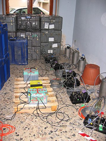
Pre-deployment or “huddle” testing of equipment is a critical step in preparing for any field-based scientific deployment. This process involves testing most or all components of a typical field station, for multiple stations, simultaneously in a centralized location. The number of systems that can be tested in parallel depends primarily on available personnel and workspace.
Huddle testing can reduce the time and cost associated with fieldwork, minimize the likelihood of returning to correct issues, and greatly improve consistency across deployment teams. Most importantly, it increases the chances of successful equipment performance once deployed.
Testing typically involves assembling key components of each station—such as sensors, data acquisition systems, GPS modules, and power systems—powering them up, collecting data overnight, analyzing the results for anomalies, and packing the equipment ready for deployment. While not all physical components (e.g., mounting hardware or enclosures) need to be set up during testing, field crews should be familiar with how these are assembled and used.
As testing concludes, all field personnel should take part in the setup of the first complete station to ensure consistency in deployment practices across teams.
Purpose of huddle-testing
Huddle-testing serves several goals:
- Inventory and confirm all shipped or supplied materials (e.g. Items shipped from EPIC and PI-supplied materials).
- Visually inspect components for damage sustained during transit.
- Verify system integration and compatibility of components.
- Provide additional hands-on training for deployment teams.
- Ensure familiarity with standardized installation procedures.
- Allows triage of marginally-performing station components
- Update necessary system databases (e.g., satellite/GNSS lock).
- Provides the opportunity to charge all batteries before deployment
Requirements
Testing can be conducted in any location with a stable, level surface—ideally indoors on the ground floor for ease of access. Overnight testing benefits from reduced environmental noise and should be conducted in a secure, weather-protected space with good sky visibility or access to windows for GPS signal reception. Easy access to transit cases and test equipment is essential for efficiency.
Set-up
Construct the station: As components are unpacked, inspect each for visible damage. Layout should minimize tripping hazards and protect sensitive items, especially sensors. For example, place the sensor under a table while placing other components on top, if needed. If space allows, keep the transit cases close to the station equipment being tested. Allow sufficient space between stations for safe personnel movement.
There will be a lot of cabling, so good cable management can be practiced and refined at this stage.
Orient and level the sensor: All the sensors being huddle-tested should be oriented in the same direction, with no requirement that they all face True North. This enables subsequent analysis by visual correlation of waveforms recorded by adjacent sensors.
GPS: Lay out the GPS antenna and cable. If indoors, and unless the roof is radio-transparent, the antennae will have to be placed to receive the satellite signals, e.g., on a window sill or cabled through to outside the building. When supplied by the EPIC, GPS was probably last locked in Socorro, NM, and could take a considerable time to lock onto the current satellite constellation. Once locked, subsequent locks during field deployment will be relatively rapid.
Apply power: Connect all subsystems, check value and polarity of power subsystems, then power up the station. With the Clie or equivalent, check that the programming of the datalogger (if being used) is for the current experiment. Then apply power to the sensor and unlock it.
EPIC-approved installation sheets may be useful!
Allow the huddle-test to run overnight. The following morning, upload the data to a laptop and examine the state-of-health (SOH) and waveform data (See Analysis section). If the go/no-go state of a station component is undecided, leave the station running additional nights.
If SOH indicate a healthy DAS and associated subsystems, and the sensor records data similar to others in the huddle-test, lock the sensor, power down the station and carefully pack all equipment in their transit cases. The station is now ready for transport to the field.
All components that fail should be red-tagged with a description of the problem and not used in the experiment unless the EPIC or PI suggests that is OK to do so. The EPIC should be notified of the problem and the component’s serial number
If a component is suspect, replace it and consider installing the marginal component at a “marginal” site. E.g., a noisy sensor could be marked for installation in an urban or naturally noisy site.
Analysis
Use EPIC-recommended techniques to offload the overnight data from the DAS, convert to miniSEED, and use the EPIC-recommended graphics tool pql to view the waveforms.
Key features in the data to check are:
- Look at SOH data (timing, power/current draw, etc.)
- Look for timing errors between stations
- Look for dead/reversed-polarity/noisy channels
- Look for pinging (on Galperin sensor designs, the pings will be resolved on all 3 components)
- Look at the same waveform channels for different sensors in several frequency bands but focus on the micro-seismic band (0.1-0.5Hz) where amplitudes and waveform character should be similar across sensors,. Other filters include teleseismic events (0.03-0.08Hz) and high-freq cultural/local events (1-6Hz).
- If an earthquake event is recorded, check that waveform amplitudes correlate and have the same amplitude
- Look for rapid drifting of mass-positions
| Attachment | Date | Size |
|---|---|---|
| 08/28/12 3:53 pm | 67.73 KB |